Halo antenna for 70Mhz
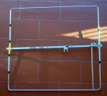 Photo 1
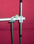 Photo 2
 Photo 3
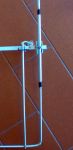 Photo 4
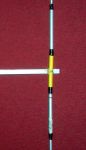 Photo 5
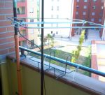 Photo 6
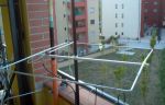 Photo 7
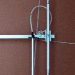 Photo 8
 Schema

Concepts
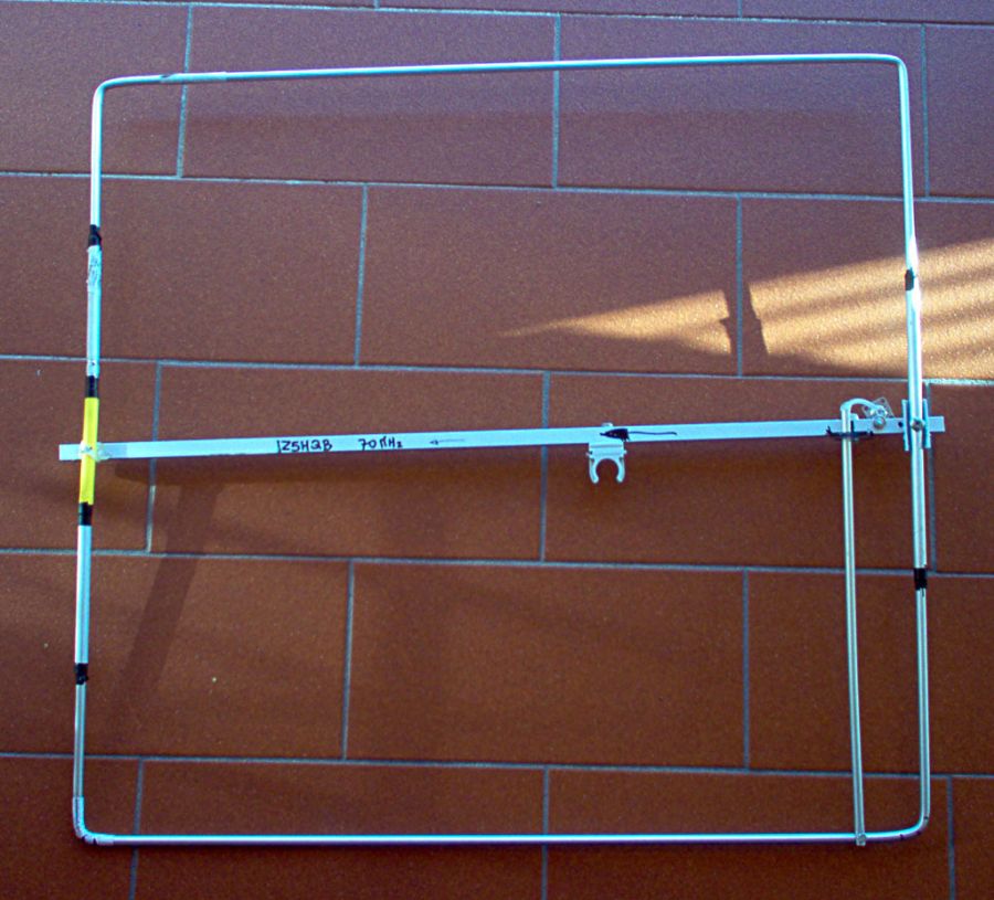
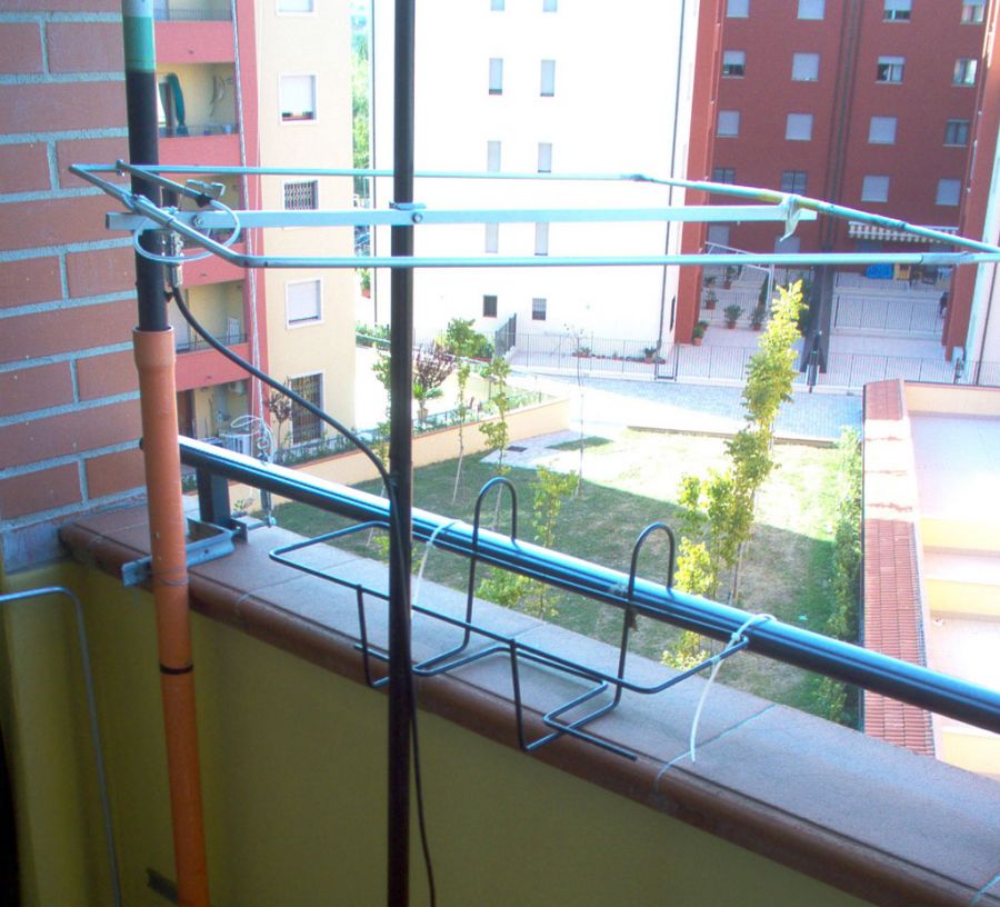
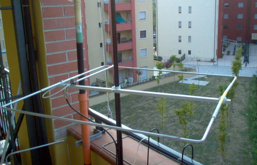
The halo is an omni-directional antenna with horizontal polarization. This is practically a horizontal loop, namely a half-wave folded dipole, with its endings slightly separated. The feeding is done through a system called gamma-match with the condenser obtained by inserting the central core of rg58 cable including the insulator, inside the aluminum tube that forms the gamma-match.Assembling
Based on a commercial model, it was reproduced using aluminum tubes from 4 and 6 mm (sold in DIY stores). The boom (H) is made with an aluminum profile 10/10 mm square section. If you are using anodized aluminum, remember that it should be grinding to all points of contact for an improved electrical conduction.
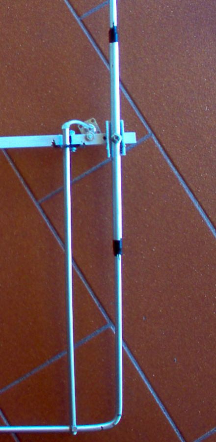
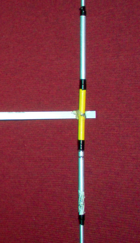
The dimensions below can be modified during implementation to match the materials used in construction. But the important is to maintain unchanged the distance E-F and B-C. (Photo 4 and Photo 5)
The E-F segment is composed of an insulating material (PVC or wood) (Photo 5).
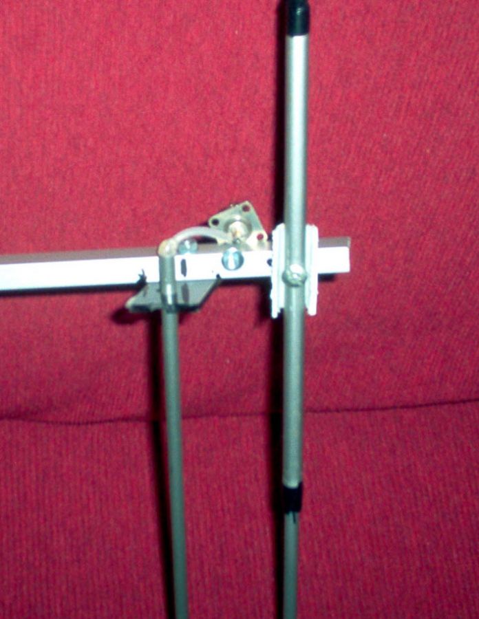
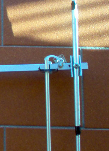
The dipole is connected to the boom in the A-B side, through a screw with an insulator between the boom and the dipole. (Photo 2)
The gamma-match (C-G) (photo 4) is electrically connected at the point C with the dipole and isolated in G by a distancer from the PVC boom. In this point it is connected the connector cable with the ground attached to the boom, while the central core is soldered the wire (rg58) with which the tuner-capacitor is done. (Photo 8)
Calibration:
For calibration can be used to a simple swr meter, find the lowest point of swr by inserting or removing the wire inside the tube (C- G gamma-match). With the above dimensions has been achieved swr values of 1:1 from 70,100 to 70,300.